
Requirements: An optical bench with uprights for holding lens, mirror and two needles, two needles (pins), a thin convex lens, a convex mirror, index needle (may be a knitting needle or a pencil sharply pointed at both ends), a meter scale and a spirit level.
Theory: A convex lens L1 converges the light rays starting from the object AB to form a real and inverted image A′B′ at position I1 [Fig. E 12.2(a)]. If a concave diverging lens L2 is inserted between the lens L1 and point I1 as shown in Fig. E 12.2 (b), for concave lens L2 image A′ B′ behaves as virtual object. A real and inverted image A′′ B′′ is formed at point I2 by the diverging lens L2. Thus, for the concave lens L2 the distances O′ I1 and O′ I2 would be the distances u and v, respectively. It is important to note that the focal length of convex lens L1 must be smaller than the focal length of the concave lens L2. The second image A′′ B′′ is formed only when the distance between lens L2 and first image A′B′ is less than the focal length of L2.
The focal length of the concave lens L2 can be calculated from the relation
Here for the concave lens both distances u and v are positive and since u will be found to be less than v, f will always be negative.

Procedure:
1. In case, if the focal length of the given thin convex lens is not known then rough value of its focal length (fL) should be estimated first to ensure that its focal length is less than that of the concave lens.
2. Place the optical bench on a rigid platform and using the spirit level, make it horizontal with the help of levelling screws provided at the base of the bench.
3. Place the uprights mounted with pin P1 (object pin), convex lens L1, and another pin P2 (image pin) on the optical bench. You may put a small piece of paper on image pin P2 to differentiate it from the image of object pin P1 [Fig. E 12.2(a)].
4. Check the col-linearity of the tip of pin P1, optical center O of convex lens L1, and the tip of image pin P2 along a horizontal straight line which is parallel to the length of the optical bench. In this condition the planes of lens and both the pins would be perpendicular to the axis of the lens.
5. For the determination of the index correction, bring a mounted pin close to the concave lens L2. Adjust the index needle (a sharp edged knitting needle would also serve the purpose) horizontally such that its one end touches one of the curved surfaces of the lens and the other end touches the tip of the pin. Note the positions of the two uprights on the scale provided on the optical bench. The difference of the two would give the observed length of the index needle. The actual length between the tip of the pin and optical
center O′ of the lens L2 would be length of the index needle (as measured by a scale) plus half of the thickness of the lens at its
optical center. The difference of the two lengths is the index correction. (If the concave lens is thin at the center, its thickness at the center can be ignored).
6. Separate the object pin P1 from the convex lens by a distance slightly greater than the focal length fL of the lens.
7. Locate its real and inverted image at point I1 on the other side of the lens by removing the parallax between the image pin P2 and image of the object pin P1 [Fig. E 12.3(a)].
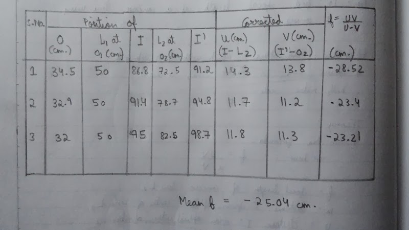
8. Read the positions of the uprights holding the object pin P1, convex lens L1, and image pin P2 (i.e. point I1). Record these observations in Table E 12.1.
9. From now on, do not change the position of the convex lens L1 and the position of the object pin P1. Insert the concave lens L2 in between the convex lens L1 and image pin P2. Now the image of object pin will shift further from the convex lens L1 to a point I2(say). Adjust the position of the concave lens so that the point I2 is sufficiently away from the point I1.
10. In case the image formed by the combination of convex and concave lenses is not distinctly visible, try to see it on moving the concave lens nearer to the point I1 and to locate the image by using a pencil held in hand, and keeping the image pin P2 at point I1 as a guide to decide which way to shift the concave lens L2. After having seen the clear image at point I2 and ensured that it lies within the range of the optical bench, move image pin P2 to locate the image (or point I2) more accurately using the method of parallax [Fig. E 12.3(b)]. Since the image forming at I2 is quite enlarged, it can be blurred.
11. Note the position of uprights holding the concave lens and image pin P2, i.e., point I2. Note the readings in the Observation Table.
12. Change the position of upright holding the object pin P1 and repeat the steps 6 to 10. Take five sets of observations.
OBSERVATIONS:
1. Focal length of the convex lens, fL = ... cm
2. Length of the index needle as measured by the scale, s = ... cm
3. Thickness of the thin concave lens (given) at its optical centre,
t = ... cm
4. Actual length between the optical centre O of the lens and tip of the pin,
l = s + t/2 = ... cm
5. Observed length of the index needle, l′
= Distance between the pole of the lens and tip of the pin
= Position of lens upright - position of pin upright on the scale
=......cm.
RESULT:
The focal length of the given concave lens is (f ± Δf) = ... ± ...cm.
Here f is mean value of the focal length.